| Remove the seat, fuel tank, and right side access panel. Both lowers may now be removed as a unit and set aside. With the lower bodywork off, the pipes may now be removed and internal motor damage may be visually inspected through the exhaust port. ( Although it can't always be seen through the exhaust port, there is a good chance that you'll be able to see score marks on the piston's exhaust side. ) |
|
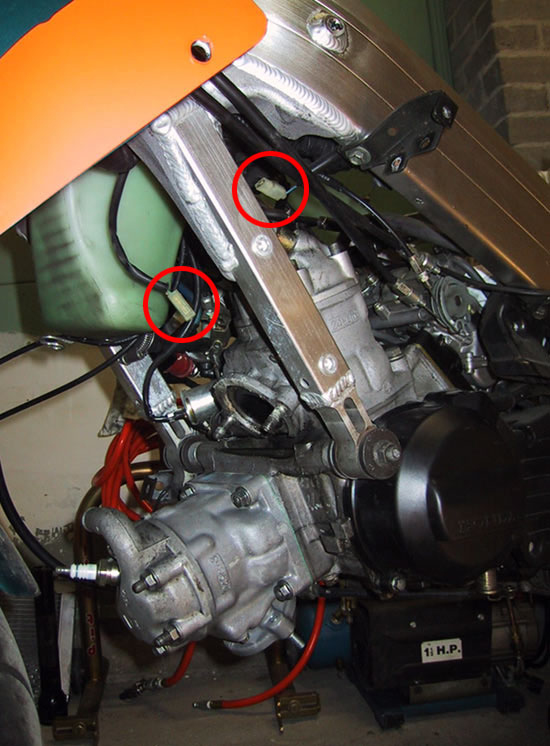
Drain the cooling system and remove the radiator and coolant overflow tank. ( Be mindful of the horn at the top left as the radiator may swing out and contact it when loosened, bending fins. ) Take note of the two leads attached to the thermostat housing when removing it. The thermostat housing is held in place by the topmost nut on the coolant tank. |
 |
The black water pump splitter/cover will need to be removed as well. |
 |
Loosen the choke and lock levers from their bracket, ( it is not necessary to remove the cables ), and remove the airbox, blocking off the carbs and fuel line. It's advisable to remove the battery at this point and place it on a maintainer/charger as a strong spark will be necessary when cranking the rebuilt engine. |
Front Head and Cylinder Removal
 |
The exterior power valve assembly can be removed as a unit without disturbing its setting. Remove the reverse thread center nut from the shaft and hold the free part of the assembly clear while loosening the bolts holding the bracket to the cylinder and swing the assembly out of the way. ( For assembly purposes, each bracket has an "F" or "R" stamped in it to prevent confusion ) |
 |
Remove the spark plug and loosen the cylinder head nuts in a star pattern, moving from one nut to the nut most opposite it. The head may be pulled clear and set aside, exposing the piston crown. Turn the engine over by hand until the piston is at the top of its stroke. (New piston and cylinder shown for clarity) |
 Loosen
the cylinder base nuts in the same manner as the head nuts. The cylinder
will likely be stuck to the case by the gasket. Rather than pry on the cylinder,
damaging both the cylinder and case gasket surface, gently tap the cylinder loose with a rubber/shot filled
mallet. This is best accomplished by working around the cylinder as best
as possible and tapping on the bulges where the bottom of the head studs
are. Be mindful of the transfer ports ( bulges on the bottom sides ) as
a hefty blow could damage a cylinder. The key is to work lightly all
the way around remembering that several light hits can be performed in succession
whereas one severe blow can not be taken back. Once loosened, the cylinder
may be removed by hand. The cylinder may be rocked fore and aft to bring
it free from the studs but rocking it from side to side should be avoided.
( Fore and aft is the same direction that the piston pivots on the rod.
) Loosen
the cylinder base nuts in the same manner as the head nuts. The cylinder
will likely be stuck to the case by the gasket. Rather than pry on the cylinder,
damaging both the cylinder and case gasket surface, gently tap the cylinder loose with a rubber/shot filled
mallet. This is best accomplished by working around the cylinder as best
as possible and tapping on the bulges where the bottom of the head studs
are. Be mindful of the transfer ports ( bulges on the bottom sides ) as
a hefty blow could damage a cylinder. The key is to work lightly all
the way around remembering that several light hits can be performed in succession
whereas one severe blow can not be taken back. Once loosened, the cylinder
may be removed by hand. The cylinder may be rocked fore and aft to bring
it free from the studs but rocking it from side to side should be avoided.
( Fore and aft is the same direction that the piston pivots on the rod.
) |
 |
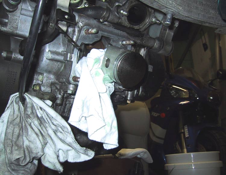
Once partially removed, a clean rag should be stuffed around the rod to keep the rod from dropping against the case, ( and possibly becoming damaged ), and to keep foreign objects from entering the case while the crank is exposed. |
 |
At this point the circlips retaining the wristpin can be removed from the piston with a pair of needlenose pliers. The easiest method is to use a small screwdriver or the pliers to turn the circlip until one end is over the machined cutout in the piston. The end can then be brought out of the groove with the rest of the circlip following. How difficult the removal will be will depend upon the condition of the piston. In this case, considerable effort was required as the piston was deformed when the cylinder seized. |
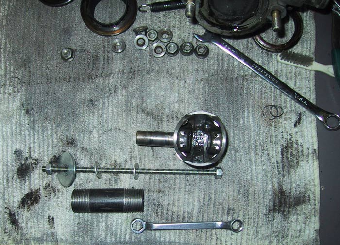 |
Removing the wristpin can be accomplished by assembling a wristpin
puller,as shown in the following images, out of parts commonly found at
hardware stores, for less than the cost of a tank of fuel. The puller
shown consists of a length of "allthread," three washers, two nuts, and a
pipe nipple. ( It is advisable to opt for a length of plastic/PVC pipe
unless the piston is to be discarded. ) Before using the puller, be sure
to check that the wristpin will clear the washer on the business
end.
Do not try to hammer or pry out the wristpin against anything other than the piston. Doing so can bend the rod and would require a complete engine overhaul. |
 |
Be
sure to center the puller over the wristpin, so as not to damage the rod
small-end and work slowly, periodically checking the progress of the
wristpin. It is not necessary to remove the pin entirely as once it has
cleared the rod small-end the piston will be free.
In this case, although the piston had seized primarily on the exhaust side, both the left and right side had made contact with the cylinder wall as well. Once cooled, the piston shrank around the wristpin which resulted in the piston chipping during wristpin removal. This was of no concern as a decision had already been made to replace both pistons. |
 |
Once
the piston is removed the small-end bearing can be easily pushed out with
a finger and the bearing surface cleaned with a clean, dry
cloth.
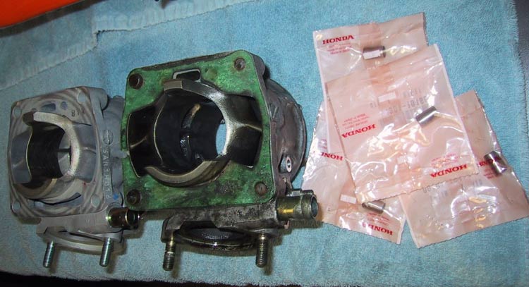
The case/cylinder mating surface will now require removal of any old gasket material adhering to the surface. Great care should be taken not to damage the surface as an air leak could result if a proper seal is not achieved upon reassembly. A flexible putty knife works well as an inexpensive gasket scraper and can be easily sharpened with a wetstone held directly against the end, like a T; ( this technique results in two good, blunt edges at the end of the knife as opposed to one sharp edge which may damage the surface. ) |
 |
Take
care when scraping the front cylinder surface as the seam where the cases
meet is exposed on either side and presents an excellent opportunity to
damage the surface. Patience and a little care will be rewarded with a
nice surface.
If the surface does become lightly damaged Yamabond ( available from Yamaha dealers ) can be used when installing the new gasket. Severe damage will mandate a visit to the machinist or replacement. |
 |
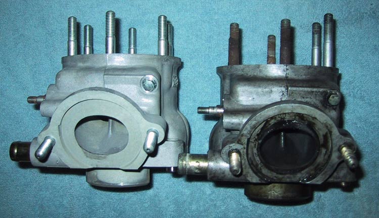
Prior
to installing the front cylinder, the two longer, left side, studs will
need to be removed and transferred to the new cylinder. The studs will
most likely have galled in place on the old cylinder and be very difficult
to remove. Two of the head nuts can be place on a stud and jammed together
so a wrench may be used to remove the studs.
To overcome the galling, a plumber's soldering torch can be used to heat the studs and ease removal. The goal is to heat the stud without heating the cylinder as such a rapid heating of only one area of the cylinder may cause it to deform. Apply the torch to the nuts on the stud for a few seconds. Water/spit on the stud after heating will immediately boil off while the cylinder will remain at room temperature. The stud can then be easily loosened with a wrench and removed from the cylinder. The two locating dowels located on the bottom of the cylinder will need to be transferred to the new cylinder or replaced with new. These dowels properly align the cylinder with the crankcase, and thereby crank, and are the same part as used on CR125s. |
 |
Before installing the pistons, the rings will need to be gapped.
This refers to the gap between the ring ends when they are in the cylinder
and varies by manufacture and application. Once gapped to a cylinder, it's
advisable to keep track of the rings to ensure that they are installed in
the same cylinder when the motor goes back together.
The easiest way to measure the gap is to place the ring in the cylinder with the 'N' side facing the cylinder top and push it up into the cylinder evenly with the piston. Once in the cylinder, the gap between the ring ends can be measured with a feeler gauge perpendicular to the cylinder wall. Ring end gap: 0.30-0.45 mm, not to exceed 0.50mm If the gap is too large, new rings are in order. If the gap is too small, the ring being measured can be removed and an ignition file can be used on either end to take material off until the gap is within specification. |
Checking the crank
 |
It can be
determined if a full tear-down and rebuild is required at this point by
checking the crank thrust clearance as an indicator of bottom-end
wear.
The rod big-end sits between two thrust washers, which control the amount of thrust, or lateral play, the big-end has. This clearance can be measured with a feeler gauge as shown and should be within spec. thrust washer clearance: 0.50-0.71 mm not to exceed 0.85mm If the crank is out of spec., a complete engine overhaul and crank rebuild is in order as excess lateral play will be magnified at the rod small-end allowing the piston to move out of line with the cylinder bore. |
 |
One of the circlips can be installed into the new piston. Be sure that the opening points up, or is closest to the piston crown, and that the circlip seats properly in its groove. The circlips may be easily pushed into place with a thumbnail. |
 |
The
rings can now be installed into the piston with the 'N' facing up, or
towards the piston crown, and the gap toward the piston's intake
side.
Note that the rings are different, although it is very difficult to tell the difference without comparing the rings side-by-side. When viewed from the end, the top ring has a keystone shape, while the bottom ring has a square shape. |
 |
Ensure that the
small-end bearing surface is still clean and give the small-end bearing a
thin coating of fresh two-stroke oil and place it in the small-end. Coat
the wristpin with two-stroke oil as well and start it in the
piston.
Place the piston over the small-end with the 'IN' facing towards the intake side which is opposite the side with the powervalve and exhaust manifold. ( If you are reusing pistons, the intake side is the side of the piston with the ring gaps and ring locating pins. ) Once the wristpin is fully pushed home, the second circlip can be installed in to the piston in much the same manner as the first. |
 |
Coat
the two new cylinder locating dowels with two-stroke oil or grease and
place them into the new cylinder. Give the new base gasket a thin coating
of two-stroke oil and place it on the cylinder base.
Give the inside of the cylinder and the piston and rings a thin coating of fresh two-stroke oil and line the cylinder up over the piston. Compress and maintain the orientation of the rings with one hand while guiding the cylinder straight over the piston with other hand. Avoid turning the cylinder as this may upset the rings and cause them to gouge the cylinder wall. Work as slowly as necessary and don't force anything into place. Once the cylinder is home over the case, the 4 nuts holding the cylinder to the case can be finger tightened. |
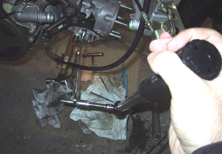 |
The nuts need
to be torqued down to spec.
cylinder base nuts: 2.5 kg-m (~18 ft. lb.s) Be sure to work on opposite corners in sequence, ( in other words, do not torque the nuts on one side and then the other, work from one corner to it's opposite. ) Once the cylinder is torqued down, carefully turn the motor over by hand while watching and listening for any binding. [If the cylinder went on easily, chances are it's fine - if forced, it might have snapped a ring.] Turn the engine to TDC ( Top Dead Center ) and wipe any excess oil from the piston crown with a clean rag. Method for torquing nuts a torque wrench can't reach shown left. Note that the torque wrench must be held perpendicular to the wrench. One of the removed studs, with jammed nuts, was used to connect the torque wrench to the wrench in this image. |
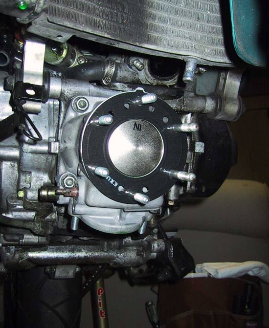 |
Place the head
gasket over the studs and onto the cylinder. A new gasket will read 'EXUP'
on one side which translates to 'EXhaust side and
UP.' The gasket won't fit with the 'EXUP' mark directly over
the exhaust manifold though. Orient the tab on the intake side of the
gasket directly over the tab on the intake side of the
cylinder.
The head can now be placed on the cylinder and the nuts finger tightened. The nuts need to be torqued down to spec. cylinder head nuts: 2.2 kg-m (~16 ft. lb.s) Again, be sure to work on opposite sides, moving from one side to the other in a star pattern. This ensures that the head is brought down against the cylinder evenly and prevents the head from warping while being torqued down or in use. Once the head is torqued down, the motor can be turned over by hand and the wonderful sounds of good vacuum and compression can be heard. A new spark plug should now be gapped and installed in order to prevent anything from entering the cylinder through the hole. Installation of the power valve assembly is the reverse of removal. |
 |
Rear cylinder
overhaul is generally accomplished in the same manner as the front
cylinder so only information unique to the rear cylinder is presented
here.
If not already removed, the thermostat housing will need to be removed in order to remove the coolant line to the rear head. The coolant line at the cylinder base is most easily removed after removing the black plastic water pump cover. The spark plug is most easily accessed, either through the side panel or from beneath the tank, with a box wrench. |
 |
Take special
care to clean the area behind the cylinder prior to removal. The angle of
the case behind the rear cylinder will almost surely cause any debris to
fall into the open case as the cylinder is removed.
Once the cylinder is loosened, the motor can be turned over by hand until the piston is at a lower point in its stroke. The cylinder can then be rocked forward and pulled clear of the piston and oil tank. Take care not to damage the rod on the case or piston skirt. |
 |
Note orientation of head gasket and piston. The gasket's "EXUP" facing forward, tab aligned over rear of cylinder, and the piston's "IN" towards the rear of the cylinder. |
 |
Prior to
refitting the pipes, turn the motor over slowly by hand and visually
inspect the pistons and rings through the exhaust ports to ensure that
everything moves freely and looks as it should. High temp silicone sealant may be used on the gasket side of the exhaust flange in an attempt to reduce seaping. It shouldn't be used on the cylinder side as it will eventually deteriorate and may be sucked back into the cylinder with a reflected charge. |
| The moment of
truth is at hand and it's time to start the motor for the first
time. The compression should be significantly improved and the engine will require more effort to start. The oil used during assembly to protect and pre-oil the new surfaces will now work against the engine running and may foul the spark plugs. It will be necessary to run the engine until this excess has worked it's way through the system, replacing/cleaning the plugs as necessary. Great debate has risen regarding the best method for running an engine in. Some important things to bear in mind are:
|
| tools
required:
|
parts
required:
|
Disclaimer
: I am not reasonable for any troubles that may happen as a result of this.
It is always
best to have a professional mechanic do the work. I accept no responsibility
what so ever.